How Does a Non-contact AC Voltage Detector Work?A magnetic field is produced around a current carrying conductor and if current through the conductor is alternating current (AC), the magnetic field produced varies periodically. A non-contact AC voltage detector detects the changing magnetic field around AC energized objects.
This non-contact AC voltage detector uses NPN type transistors in order to detect voltage. A transistor has three terminals - collector, emitter and base. Collector to emitter current is controlled by the base current. When there is no base current, no collector to emitter current flows. Thus, a transistor acts as a switch. It can be 'ON', it can be OFF or in-between. The ratio of collector current to base current is known as the gain of a transistor. Normally, gain of 2N3904 is about 200, i.e. collector to emitter current can be as high as 200 times the base current. If we connect the output of one transistor to the base of another transistor, the total gain would be multiplication of the two i.e. 200x200 = 40000. Thus, if we connect three transistors in such configuration, the total gain would be 200x200x200 = 8,000,000. Therefore, an extremely small signal can be used to switch ON a normal circuit by using such configuration of transistors. In our circuit, an antenna (copper wire) is connected to the base of first transistor. When we place this antenna near an object that is AC energized, a small current gets induced into the antenna due to electromagnetic induction. This current triggers the first transistor and output of the first transistor triggers the second and third. The third transistor switches ON the LED and buzzer circuit, indicating that AC voltage is present. |

Building Your Own Non-contact AC Voltage Detector Use the following circuit diagram as a reference to place the components on the Printed Circuit Board (PCB). 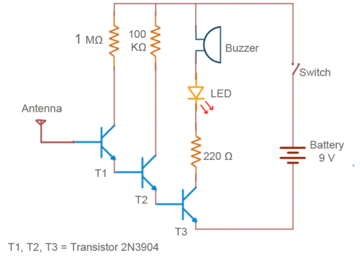
|
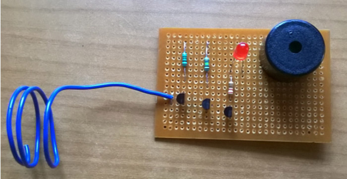
Mount the components on the PCB and solder them one by one in the appropriate places as per the circuit diagram.
Connect one terminal of the copper wire and to the base of the first transistor. The copper wire will act as an antenna. Tip: For improved sensitivity use about 10 to 12 cm of wire.
Make two holes in the case - one for the switch and another for removing the copper wire. Attach the switch to the box.
Put the circuit inside of the box. Take the antenna wire outside, twisting it into a spiral shape. Attach it to the box using adhesive tape.
Connect the wires to the switch as per the circuit diagram.
Attach the wires of the 9V battery holder to the circuit according to the schematic. The battery symbol should have a plus on one side for polarity.


